Search This Blog Here

Showing posts with label Transformers. Show all posts

What is the dc transformer? How it works?Explain


Chopper you can call it as a DC transformer. Chopper main function is to step up or step down the voltage levels.  By using thyristors allowing the supply for on time and block during off time to load, which will give u variable and down voltage.

To get step up voltage, need energy storage devices like inductor or capacitor


why transformer ratings are taken in 11kv 22kv 33kv but not in 10,20,30kv


ANS:These are the optimal voltages.

can u tell the difference between star - star transformer and delta to delta transformer


This is related to design of transformer,
  1. Star would be better for High voltages, 
  2. Delta would be better for high currents.
  3. It is an optimization in cost and technical.

What is a Bus PT and what is the function of it

PT is a potential transformer, which would reduce the voltage to measurement levels i.e. 110V or 220V from line voltage 220Kv, 132 KV, 33KV etc..

When this is PT is connected to bus bar in the switchyard then we call it as a bus PT.

What is the dc transformer? How it works-Interview Questions

Chopper you can call it as a DC transformer. Chopper main function is to step up or step down the voltage levels.  By using thyristors allowing the supply for on time and block during off time to load, which will give u variable and down voltage.

To get step up voltage, need energy storage devices like inductor or capacitor

Sub Station Air Switches

Substation Air Switch

Substation air switches are mechanical switching device that are used for changing the
connections in a circuit. The switches are required to carry normal load current
continuously and short-circuit current for short period of time. Substation air switches
are used for circuit breaker isolation, power transformer isolation, electrical equipment
bypassing, and bus sectionalizing.
Figure 3-5, 3-6, 3-7, and 3-8 shows different type of
outdoor air switches.

Figure 3-5: Hook Stick-Operated Disconnecting Switch
Figure 3-6: Three-Phase Gang-Operated Disconnecting Switch with Horn Gaps and Grounding Switch
Figure 3-7: Three-Phase Double Side-Break Disconnecting Switch with Motor Operator
Figure 3-8: Fused Disconnect

The operating mechanisms are bonded directly to the operator mat/platform with a 4/0
copper ground conductor to ensure that the operating personnel’s hands and feet will be
maintained at the same potential. Figure 5-22 and 5-23 shows horizontally mounted
double break switch with grounding and horizontally mounted double break switch.

Figure 5-22: Horizontally Mounted Figure Double Break Switch with Break Switch


5-23: Horizontally Mounted Double


Grounding Switch

Table 4-8 lists the phase spacing of various types of outdoor air switches.

The minimum metal-to-metal clearances should be maintained at all times with the switches
in the open, closed, or anywhere between the open and closed positions.

Table 4-8: Phase Spacing of Outdoor Air Switches

SUBSTATION SF6 GAS CIRCUIT BREAKERS

Substation SF6 Gas Circuit Breakers

A circuit breaker closes and opens an electric circuit under both load and fault
conditions. There are two types of circuit breakers, dead tank and live tank. Dead tank
circuit breaker means that the external source and load connections are made through
conventional bushings, circuit breaker tank and all accessories are maintained at
ground potential. Live tank circuit breaker means that the interrupting mechanism is
mounted on an insulating porcelain column and maintained at line potential.
Substation circuit breakers are also classified as three-pole-single-throw and
independent pole operation. Three-pole-single-throw circuit breakers utilize one
mechanical device to trip all three poles together and independent pole operation circuit
breakers utilize one mechanical device per pole to trip individual pole. Figure 3-10, 5-2,
and 5-3 shows the power circuit breaker one line, dead tank, and live tank breaker.
Figure 3-10: Circuit Breaker


(Shown with Bushing-Type CTs and Reclosing Relay)

Substation Power Transaformer | Estimation | Caluculation in Sub Stations

1
CPM Scheduling,
Basic Engineering,
and Project Approach for Typical Substation EPC

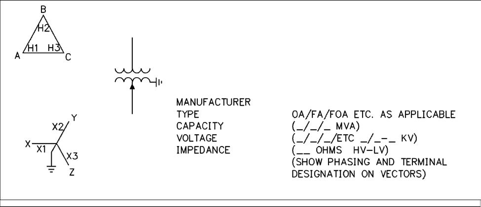
Substation Power Transformers

The substation power transformers transform one nominal level system voltage to
another. The power transformers must carry the system power flow under various
operating conditions and contingencies. Power transformers are the largest, heaviest,
and very costly piece of equipment used in substations. There are two types of power
transformers, autotransformer and multiwinding conventional transformers. A three-
phase power transformer installation can be a three-phase unit or three single-phase
units.
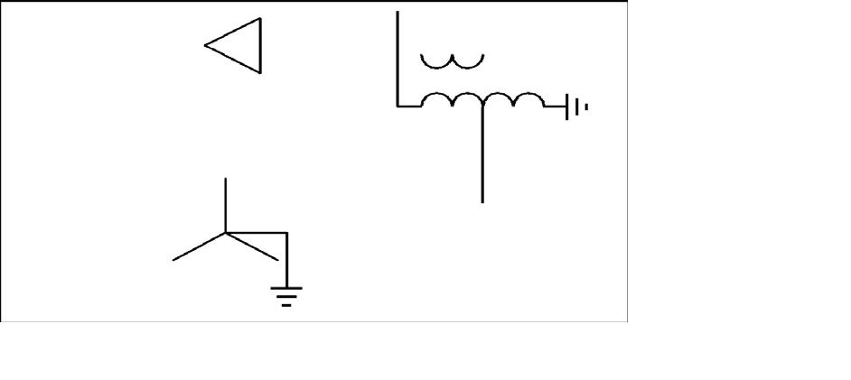
Figure 3-1, 3-2, and 3-3 shows the power transformer, three-phase transformer with
tertiary and three-phase Auto-Transformer.
Figure 3-1: Power Transformer


(Shown with Load Tap Changer on Low-Voltage Side)
1
Dewan Jamir EMGT 835, Spring 2006


Figure 3-2: Three-Phase Transformer with Tertiary


Figure 3-3: Three-Phase Auto-Transformer